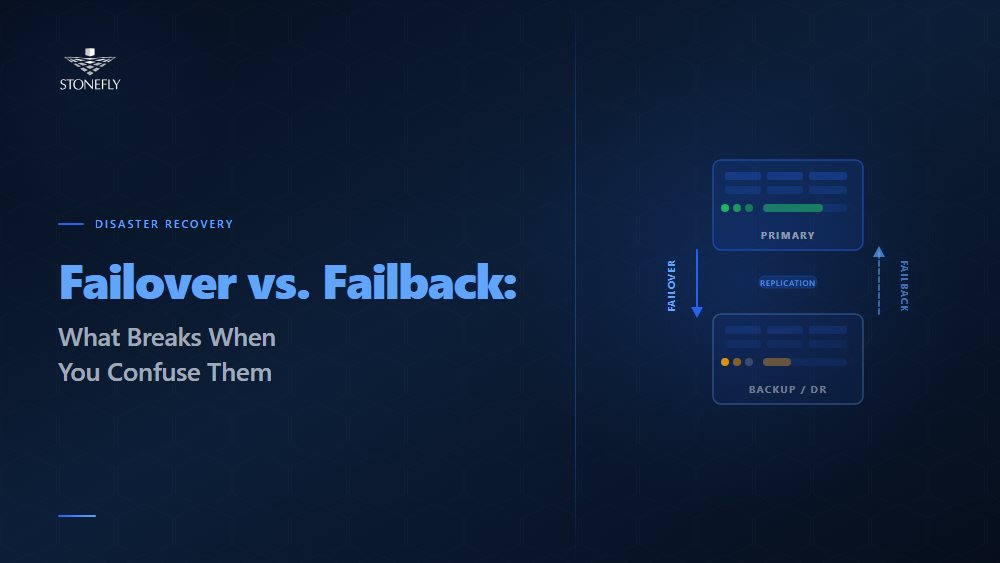
Every disaster recovery plan has a failover section. Far fewer have a failback section that deserves the name. Failover — the process of switching traffic and workloads from a failed primary environment to a standby — gets documented, tested, and rehearsed because it is the obvious immediate need during an outage. Failback — returning those workloads to the restored original environment once the incident is resolved — tends to get a paragraph at the end of the DR plan that says something like “reverse the failover steps.” That paragraph is almost never tested. It is almost always wrong.
The failover and failback difference matters because they are not mirror images of each other. Failover operates on systems in a known bad state — the primary has failed, and the objective is to restore service as fast as possible. Failback operates on systems in an uncertain state — the primary has been restored, but it has been offline during the failover period, the secondary has been running live writes, and the two environments now diverge. Reconciling that divergence without data loss or service interruption requires a different set of procedures, tools, and testing than failover does.
This blog covers what failover and failback are, where they fit in disaster recovery and business continuity planning, how recovery point and recovery time objectives apply to each, and what a complete, tested recovery architecture looks like when both halves are designed deliberately.
Failover is the process by which a system, application, or network automatically or manually switches operation from a failed primary component to a designated standby or secondary component. In the context of IT disaster recovery, failover transfers workloads — virtual machines, databases, application stacks, network traffic — from a primary site or system that has become unavailable to a recovery site or standby system configured to absorb that load.
Failover can be triggered by hardware failure, software failure, network partition, power loss, or deliberate administrative action during planned maintenance. In high availability architectures designed for sub-minute recovery, failover is fully automated: a heartbeat or health-check mechanism detects the primary failure within seconds, and orchestration software promotes the standby to primary and redirects traffic before most users notice a disruption. In disaster recovery architectures designed for site-level failures, failover may be semi-automated or manual, requiring human authorization before production traffic is committed to the DR site — a deliberate checkpoint to avoid false failovers during network blips.
The failover mechanism — the specific combination of health monitoring, detection logic, and orchestration tooling that executes the switch — is the critical engineering component in any high availability or DR architecture. A failover plan that relies on manual steps in a runbook is only as fast as the team executing it. A failover plan with automated orchestration is only as reliable as the health-check thresholds and fencing mechanisms that prevent it from triggering incorrectly.
Failback is the process of returning workloads, traffic, and operations from the standby or DR environment back to the restored original primary environment after a failover event. Where failover is reactive — triggered by failure — failback is deliberate: a planned, sequenced migration executed after the primary environment has been repaired, validated, and confirmed ready to resume production workloads.
Failback is harder than failover for a specific technical reason: data divergence. During the failover period, the secondary environment has been running live. Users have been writing data, applications have been logging transactions, and databases have been recording changes — all on the secondary, not the primary. When the primary comes back online, it reflects the state of the system at the moment of failure. The secondary reflects everything that happened after. Failback must synchronize that delta — the changes accumulated on the secondary during the outage — back to the primary before the primary can safely resume production. Do this incorrectly, and the result is data loss or, worse, split-brain between two systems that both believe they are authoritative.
This is the gap most DR plans miss. Failover procedures are tested because teams practice “the primary is down” scenarios. Failback procedures are rarely tested because testing them requires actually running the secondary as primary for a period and then executing the reconciliation — a more complex and time-consuming test that most organizations defer indefinitely. The result is that when a real failover event requires a real failback, the team is executing untested procedures under pressure, which is when untested procedures fail.
| Dimension | Failover | Failback |
| Trigger | Unplanned failure or planned maintenance cutover | Deliberate decision after primary is restored and validated |
| Direction | Primary → Secondary (or DR site) | Secondary → Primary (or DR site → original site) |
| Data state | Primary is failed; secondary holds last-replicated state | Secondary has live data accumulated during outage; primary is stale |
| Primary challenge | Speed — minimize RTO while preventing false failover | Data reconciliation — sync secondary changes to primary without loss |
| Automation suitability | High — automated failover appropriate for most HA scenarios | Low — failback should involve human validation before cutover |
| Testing frequency | Should be tested quarterly or per major infrastructure change | Frequently skipped; must be tested at same cadence as failover |
| Risk profile | Risk of prolonged downtime if failover is slow or fails | Risk of data loss or dual-primary conflict if failback is rushed |
| RPO implication | RPO is the replication lag at the moment of failure | RPO for failback is data accumulated on secondary during outage |
| RTO implication | RTO is time from failure detection to workload availability on secondary | RTO for failback is time to sync delta + validate primary + switch traffic |
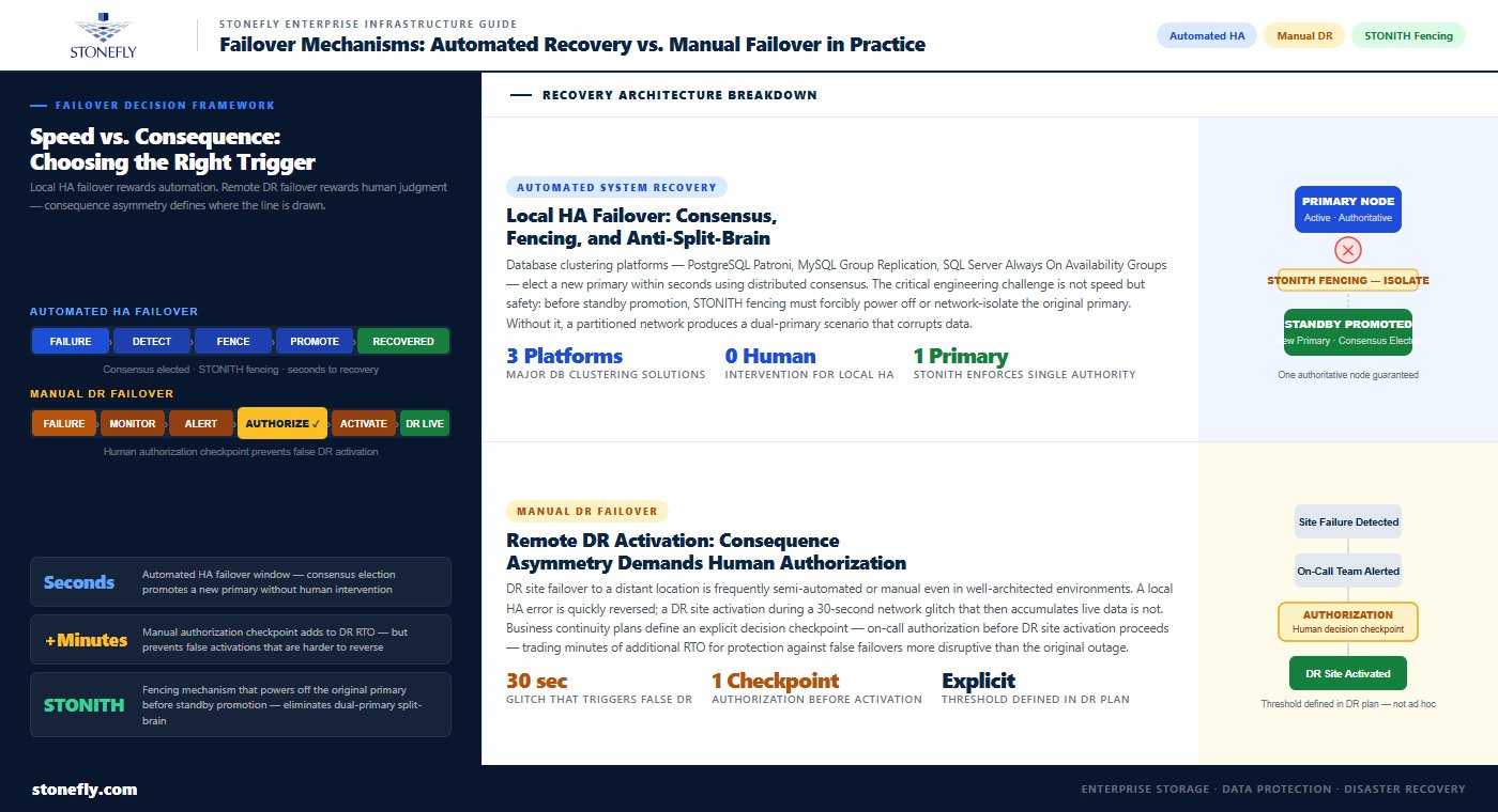
Automated system recovery — failover triggered and executed without human intervention — is appropriate for high availability architectures where the failure scenario is local (a single server, a single storage controller, a single network link) and the recovery target is well-understood and pre-validated. Database clustering solutions like PostgreSQL Patroni, MySQL Group Replication, and Microsoft SQL Server Always On Availability Groups implement automated failover with distributed consensus mechanisms that elect a new primary within seconds of detecting a node failure. Load balancers and application delivery controllers implement automated failover at the network and application tier, redirecting traffic away from failed endpoints to healthy ones in real time.
The engineering discipline required for automated failover is in the fencing and anti-split-brain mechanisms. Before a standby is promoted to primary automatically, the system must confirm that the original primary is genuinely unavailable — not merely unreachable due to a network partition that left it still running and still serving some traffic. STONITH (Shoot The Other Node In The Head) fencing mechanisms forcibly power off or network-isolate the original primary before the standby is promoted, ensuring that two nodes cannot simultaneously believe they are the authoritative primary. Without reliable fencing, automated failover in a partitioned network can produce dual-primary scenarios that corrupt data.
Disaster recovery failover to a remote DR site — as opposed to local HA failover within a data center — is frequently semi-automated or manual, even in well-architected environments. The reason is consequence asymmetry: a local HA failover that triggers incorrectly causes brief additional disruption but can usually be quickly reversed. A DR site failover that triggers incorrectly — committing production traffic to a distant DR site over a WAN link during a network glitch that resolves in 30 seconds — can cause sustained performance degradation and is harder to reverse if the DR site then accumulates significant live data.
Business continuity failover plans for DR site activation typically include a decision checkpoint: monitoring detects the primary site failure, alerts the on-call team, and presents the declared failure for human authorization before DR site activation proceeds. This checkpoint adds minutes to the RTO but prevents false DR activations that would be more disruptive than the original brief outage. The threshold for automatic vs. manual DR failover should be defined explicitly in the disaster recovery failover plan — not left to on-call judgment in the middle of an incident.
The recovery point objective (RPO) defines the maximum amount of data loss an organization can tolerate, expressed as a time interval — the most recent point to which systems can be restored. RPO is set before disaster occurs; it is an architectural constraint that determines what replication technology and configuration are required. An RPO of zero requires synchronous replication: every committed transaction must be acknowledged on the standby before the primary confirms it to the application. An RPO of 15 minutes allows asynchronous replication with up to 15 minutes of acceptable lag, which is far more forgiving of WAN latency and temporary replication interruptions.
RPO applies differently to failover and failback. For failover, RPO is the replication lag at the exact moment of failure — how far behind the standby was when the primary went down. For failback, RPO is the data accumulated on the secondary during the entire failover period. A 4-hour outage with active user writes during the failover period creates a 4-hour data delta that must be reconciled before the primary can resume production. This delta is typically much larger than the replication lag that determined the original failover RPO, which is why failback data reconciliation is a first-class engineering problem, not an afterthought.
The recovery time objective (RTO) defines the maximum acceptable duration of a service outage — how long systems can remain unavailable before the business impact becomes unacceptable. RTO drives the engineering investment in the failover mechanism: an RTO of 5 minutes requires automated failover with pre-warmed standby systems that receive continuous replication and can accept traffic immediately. An RTO of 4 hours allows a cold standby that must be started, restored from backup, and validated before going live.
RTO also has a failback dimension that is frequently unaccounted for in DR planning. If the failover RTO is 5 minutes but the failback RTO is not defined, the organization may find itself running on the DR environment for days or weeks because nobody planned a specific time target for returning to primary. That extended DR operation creates its own risks: the DR environment was sized for temporary operation, not sustained production load, and the longer it runs, the larger the data delta that must be reconciled at failback. Service recovery performance metrics should define both failover RTO and failback RTO explicitly in the disaster recovery plan.
High availability and disaster recovery are frequently conflated in IT continuity planning, but they address fundamentally different failure scenarios and require different architectural approaches. Understanding the distinction is essential for sizing the right solution to the right problem.
High availability (HA) architecture addresses component-level failures within a single site or data center: a failed server, a failed storage controller, a failed network switch. HA is designed around redundancy — every critical component has a live standby — and automation — failover to the standby happens in seconds without human intervention. HA architectures achieve RTOs measured in seconds to minutes for most failure scenarios and are appropriate for protecting against the most common failure types in enterprise infrastructure.
HA does not protect against site-level failures: a power outage affecting the entire data center, a natural disaster, a network incident that takes down the facility’s external connectivity, or a ransomware event that encrypts all storage within the site. By definition, if both the primary and the standby are in the same physical location, a site-level failure takes both down simultaneously. High availability architecture and disaster recovery are complementary layers, not alternatives — HA handles the frequent, recoverable failures; DR handles the rare, catastrophic ones.
Disaster recovery failover addresses site-level failures by maintaining a copy of critical workloads and data in a geographically separated location — a secondary data center, a colocation facility in a different metro area, or a cloud-based DR target. When the primary site becomes unavailable, DR failover activates the secondary site, restoring service from the most recent recovery point available. The RTO for DR failover is typically longer than HA failover — minutes to hours depending on architecture — because the secondary site may be geographically distant, the failover procedure requires human authorization, and the data state must be validated before production traffic is committed.
Infrastructure resilience in a complete IT continuity planning framework requires both layers: HA for operational continuity during component failures, and DR for survival of site-level incidents. The disaster recovery strategies that organizations document in their business continuity planning should distinguish explicitly between HA events (handled automatically, no DR activation required) and DR events (require human decision and DR site activation), with defined criteria for escalating from HA to DR response.
Failover testing vs. disaster recovery testing are two distinct exercises that serve different validation purposes. Failover testing — validating that HA mechanisms correctly detect failure and promote the standby — can and should be executed frequently, in many cases non-disruptively. Modern HA platforms support live migration testing: a workload is live-migrated to its standby, the migration is validated, and traffic is returned to the original host without end users experiencing an outage. This tests the failover mechanism, the monitoring detection logic, and the orchestration tooling without requiring a real failure event.
For components that cannot be tested non-disruptively, scheduled maintenance windows provide the opportunity for controlled failover tests: take a server offline deliberately, confirm the standby promotes correctly and applications remain available, then bring the original server back. Failover testing should be documented with pass/fail criteria defined in advance — not just “did it work” but “did it work within the defined RTO, with no data loss beyond the defined RPO, and did the application function correctly on the standby.”
Disaster recovery monitoring — the ongoing observation of replication health, standby readiness, and recovery point currency — is the operational layer that keeps the DR architecture trustworthy between tests. A DR plan that was valid at last year’s test but has accumulated six months of replication lag, outdated network configurations at the DR site, or standby VMs running unsupported OS versions is not actually a working DR plan. Continuous monitoring must verify replication lag against RPO thresholds, validate standby configuration currency, and alert on any condition that would prevent a successful failover.
The infrastructure monitoring strategy for a complete HA and DR architecture should cover three distinct layers: production infrastructure health (detecting failures that trigger HA failover), replication health (validating that DR standby data is within RPO thresholds), and DR environment readiness (confirming that the DR site can accept a failover activation at any given moment). Most organizations monitor the first layer well and the second and third layers poorly. The result is that the DR plan says the RTO is 4 hours, but an actual DR activation would take 12 hours because the standby environment has drifted into a state that requires remediation before it can accept production traffic.
A disaster recovery failover plan that only covers activation — how to switch to the DR site — is half a plan. A complete DR failover plan documents four distinct phases: detection and declaration (how failure is identified, who declares a DR event, and what the authorization chain looks like); failover execution (the specific steps to activate the DR site, in sequence, with assigned owners and time targets for each step); DR site operation (how the environment is managed while running as primary, including monitoring, change control, and capacity management); and failback execution (the steps to reconcile accumulated data, validate the restored primary, and return production to the original environment).
Disaster recovery execution documentation for each phase should be written at the level of detail required by someone who has never executed it before — not the person who wrote the plan, but the junior team member who picks up the runbook at 2 AM during an actual incident. Every step should specify the exact command or action, the expected outcome, how to verify the outcome was successful, and what to do if it was not. Ambiguous steps in DR runbooks are a primary cause of extended recovery times during real events.
The failback section deserves specific attention: it should document the data reconciliation approach (which replication tooling will sync the delta from secondary back to primary, how long that sync is expected to take, and how its completion is validated), the primary validation checklist (what must be confirmed before traffic is returned), and the traffic cutover procedure (how the switch is made without dropping active connections). This section of the DR plan should be tested at least annually against a realistic scenario — not a sanitized test where the secondary has been running for 30 minutes, but one where it has been running for hours or days and has accumulated meaningful data changes.
Failover and failback architectures are only as reliable as the data protection and replication infrastructure underneath them. StoneFly’s disaster recovery platforms are built to support both halves of the recovery cycle — not just the failover activation, but the data reconciliation and validated return that complete a real DR event.
StoneFly’s DR365V integrates with Veeam to deliver continuous, policy-driven replication to air-gapped, immutable backup repositories — the foundation of a DR architecture that remains recoverable even when the primary environment and its standard replication targets are compromised by ransomware. The DR365V’s immutable repositories ensure that a clean recovery point is always available for failover, regardless of what has happened to the production environment. Veeam’s orchestrated recovery capabilities support automated failover testing — spinning up recovery VMs from the DR365V repository in an isolated sandbox, validating application functionality, and tearing the test down without impacting production — enabling the regular failover test cadence that keeps the DR plan valid.
For failback, the DR365V’s replication capabilities support bidirectional synchronization: once the primary environment is restored, accumulated changes from the DR standby can be replicated back to the primary before the production cutover, minimizing the data delta that must be reconciled and reducing the failback RTO to the synchronization window rather than a full data restore. This is the specific capability that makes the difference between a failback that completes in a maintenance window and one that requires days of manual reconciliation.
StoneFly’s USS hyperconverged infrastructure provides the high-availability compute and storage layer for production environments, with built-in NVMe-backed redundancy and live workload migration capabilities that support non-disruptive HA failover testing. For organizations designing a complete infrastructure resilience architecture — HA within the primary site, DR replication to the DR365V, and validated failback procedures — the USS and DR365V together cover both the operational availability and the catastrophic recovery use cases.
Enterprise IT teams designing failover and failback architecture can explore StoneFly’s DR365V and USS platforms or contact StoneFly to discuss recovery architecture design for specific environments and RTO/RPO requirements.
Failover and failback are two halves of a complete recovery cycle, and treating only one as a first-class engineering concern leaves the other as a liability. The asymmetry matters: failover is the urgent, visible problem that organizations prepare for because the consequences of slow failover are immediate and obvious. Failback is the deliberate, planned problem that organizations defer because the consequences of poor failback planning are not visible until a real DR event forces it into production under pressure.
The measure of a mature disaster recovery strategy is not how fast failover can be executed — it is how confidently the team can return to the original environment after a failover event, with full data integrity, within a defined RTO, having tested the full round trip. That confidence comes from designing failback as deliberately as failover: documenting the data reconciliation approach, defining a failback RTO, testing the procedure against realistic scenarios, and monitoring the DR environment continuously so it is ready when it is needed. IT continuity planning that includes both failover and failback as equally tested, equally documented procedures is the standard every enterprise DR program should be held to.
Contact StoneFly to discuss how DR365V and USS support your organization’s failover and failback architecture, or to request a review of your current DR plan against recovery time and data loss objectives.


Join our mailing list to receive the latest news, updates, and promotions from StoneFly.